JCA50 Bias mod

Post custom amp, guitar and fx mods. Share details about your custom builds.

Moderators: greatmutah, GuitarBilly

Post Reply
User avatar
ironman28
Registered Member
Posts: 82
Joined: Sat Jun 01, 2013 10:46 am
Contact:

JCA50 Bias mod

Post by ironman28 »

Do not attempt this modification if you are not familiar with HIGH VOLTAGE power supplies. There are voltages inside the JCA50 that can KILL YOU or maybe your cat or your 3 year old nephew...anyway you should UNDERSTAND and FOLLOW all safety precautions. Failure to do so may result in DEATH.

Here is a mod for the JCA50 to allow external bias test points and adjustment per tube. You can then replace tubes and set the bias without removing the chassis from the head. The goals of this mod are safety and convenience. By using the cathode sense resistors to monitor the current through the tubes you eliminate the shock hazards trying to monitor plate current with an open chassis. I encourage everyone to avoid trying to bias your amp using the transformer shunt method shown in some You Tube videos. The transformer shunt method of measuring plate current is inherently unsafe. Buy a bias probe or at least install the cathode sense resistors on your amp.
The individual bias pots allow you to balance the DC currents through the OPT. Correct DC balance reduces hum and provides better bass response by reducing any standing flux in the transformer primary. Matched tube sets can help when they are matched for current draw but there still may be a 5-10% difference in the "matched" tubes. All tubes drift and matched sets are no exception. Check with your tube vendor to see if they burn in their power tubes before matching. Tubes may drift from their initial current draw over the first 10 hours of use. When installing new tubes, set the bias and let the amp idle for 4 to 5 hours then recheck the bias. The tubes will continue to drift as they age but less than the initial burn in period.

Parts

The parts for this mod can be ordered through Weber.

2 ea PNJ-P-Red Pin Jack
1 ea PNJ-P-Blk Pin Jack
2 ea wp503L 50k linear pot,screwdriver slot with locking bushing
2 ea 1 ohm 1% metal film resistor
1 ea 15k ohm 5% 1/2 watt resistor
1 ea 10k ohm 5% 1/2 watt resistor
1 ea 16uF 150VDC electrolytic capacitor
Here is a pic of the pin jacks and locking pots
Image
Procedure
First install the 1 ohm cathode sense resistors. This will allow safe monitoring of cathode current through the test points.
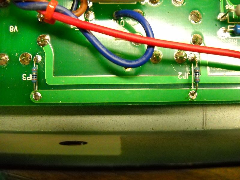
The JCA50 and 100 both have zero ohm jumpers on the circuit board that connect pin 8 (cathode) of the output tubes to ground. These jumpers are removed and the sense resistors installed in their place.
Here are the sense resistors installed
Image
I have left the resistors above the board slightly to allow attachment of the leads and also to protect the board if one of the resistors gets taken out by excessive current. I am using 10 ohm 1/4 watt resistors. The 10 ohm allow better accuracy with most budget multimeters. The 1/4 watt rating is ok for my uses as it offers a margin of protection from a shorted tube taking out the OPT. You can use a 1 watt part here if you want. Be sure to get 1% resistors if you use the 1 ohm value. I selected two resistors as closely matched as I could get them.

Select a place to install the pin jacks. I installed these in a vertical line where they would not interfere with the removal of the PCB.
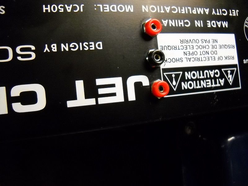
Image

Here is a shot inside the chassis. You can see how the test jacks clear the PC board on the left.
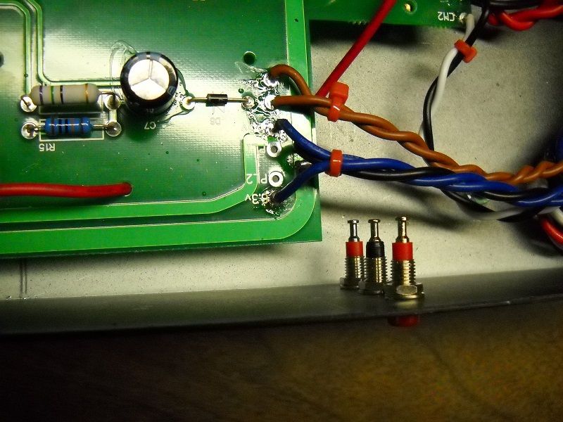
Image

Select a location for the bias adjustment pots. I placed mine on the top of the chassis where they cannot be moved without taking the back panel off. Also I wanted the leads to be relatively short and to not use space on the back of the chassis. Note how the bias pots only have two wires attached to create a variable resistor.
Image

One of the new bias pots will take the place of the original on board bias trimmer. Remove the trimmer from the board and connect the new bias pot in its place. This will be the bias adjustment for V8.
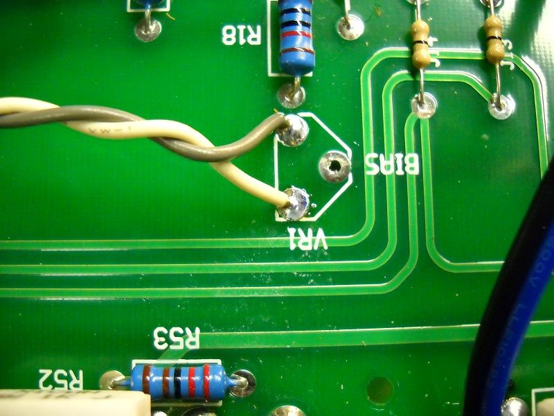
Image

Unsolder and lift one end of R13 as shown. This will be where the new bias circuit will attach to bias V7.
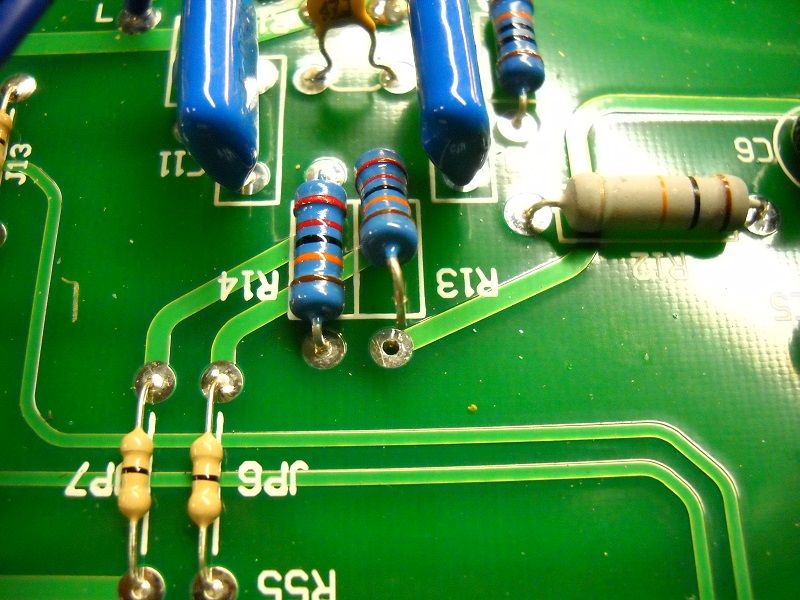
Image

For the new bias circuit you will need to construct some way to hold the additional parts. I choose a small piece of perfboard to hold the components. It is attached to the PC board with double sided foam tape. The new circuit is a replica of the one already on the board. Refer to the JCA50 power amp schematic. The new circuit consists of a 15k resistor, a 16uf 100v capacitor and a 10k resistor. The new bias pot will connect to this circuit and also the end of R13 that was lifted in the previous step. The circuit we are copying consists of R11, C6 and R18. VR1 is replaced by the new bias pot. Here is the schematic for the new bias circuit:
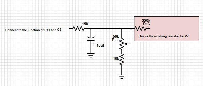
Image

Here is a shot of the new circuit after being attached. The gray and white wires go to the new bias pot
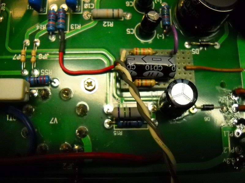
Image

Testing

Remove all tubes from the amp if you have not already done so. Leave the standby switch OFF.
Power the amp on.
check between ground and pin 5 on V7 tube with a voltmeter
You should see a negative voltage between 63 VDC and 30 VDC
Rotate the V7 bias pot while reading the voltage. Make sure it is 60VDC or higher with the pot fully clockwise
Repeat testing for V8 bias

Here is a shot of the bias pots from the outside
Image

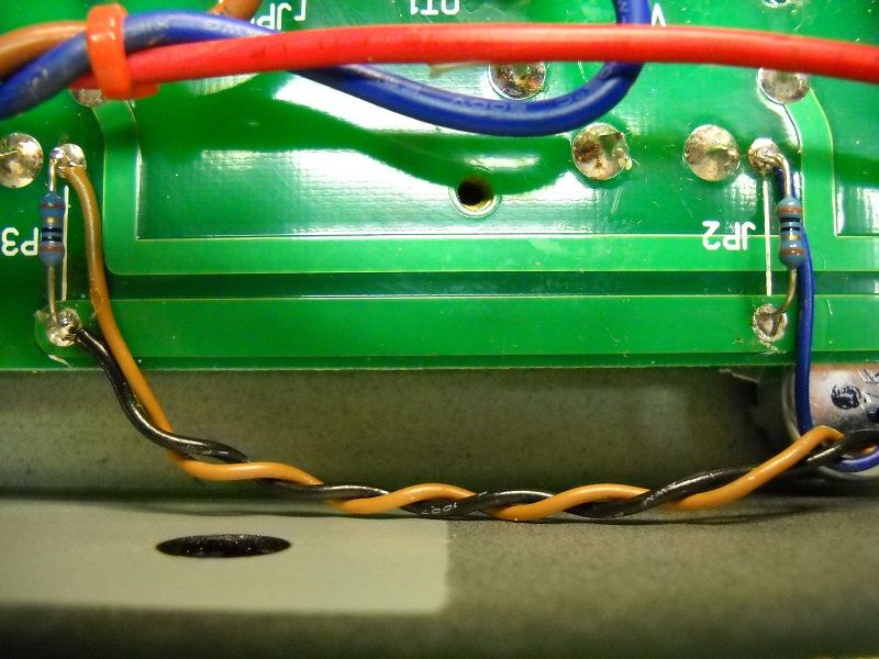
If testing is successful attach the leads from the test points to the cathode sense resistors. The black test point connects to ground and the red test points connect to the cathodes of V7 and V8 as shown here.
Image

Using the new test points

Use your normal bias procedure for new tubes.
measure your B+ voltage(you only have to do this once) and calculate the bias current for your tubes (if you dont know how to do this STOP now)
With the power tubes out check pin 5 for -DCV turn bias pots fully clockwise.
Insert power tubes- power on
Use a voltmeter connected to the test points
the voltmeter will display millivolts if you used a 1 ohm cathode sense resistor.
so 35mv = 35ma current
If you used a 10 ohm resistor add a zero
350mv = 35ma current
Last edited by ironman28 on Sat Aug 17, 2013 10:07 am, edited 2 times in total.
User avatar
Tortuga
Crystal Lettucer
Posts: 17174
Joined: Sat Jan 19, 2013 11:29 am
Location: Slow and steady, bruh

Re: JCA50 Bias mod

Post by Tortuga »

Extremely cool - definitely something I'm going to want to do to my amp. I very much appreciate you sharing this info!

I would HIGHLY suggest putting some kind of disclaimer / warning at the top of this posting - working on the inside of the amp can be lethal. I'm sure you know that, but someone else might not...

A couple of questions:
* Is there a practical benefit to changing the bias to a dual-adjustment? Is this to accommodate tubes that may not be closely matched?
* Can the B+ (or some representative of the voltage) be safely carried to a test point as well? Or do I just measure it off of one of the pins on the tube?
Co-founder of the Jet Setters 2.0 (Jet ★ City Lounge Redux)

Gear
  • CEOwLP (Sig T), Carvin DC135, Westone Spectrum SX (guitar) & GT (bass), Squier strat
  • '66 Bassman, '61 Magnatone, Mark III, 1960AX, homebrew 2x12 (C90 / EVM12L Thiele), HX Stomp, JCA50H
  • PLX GABion, SD-1, TS9, Crybaby, MXR108, Algal clone, Carbon Copy deluxe

DIY

Ostinato Rubato wrote:"That's the second boomery bro on this forum I've helped seduce to the greenside." :evil:

"Slow and steady gets to **** again eventually" :fap:
User avatar
ironman28
Registered Member
Posts: 82
Joined: Sat Jun 01, 2013 10:46 am
Contact:

Re: JCA50 Bias mod

Post by ironman28 »

GRIMESPACE wrote:Extremely cool - definitely something I'm going to want to do to my amp. I very much appreciate you sharing this info!

I would HIGHLY suggest putting some kind of disclaimer / warning at the top of this posting - working on the inside of the amp can be lethal. I'm sure you know that, but someone else might not...

A couple of questions:
* Is there a practical benefit to changing the bias to a dual-adjustment? Is this to accommodate tubes that may not be closely matched?
* Can the B+ (or some representative of the voltage) be safely carried to a test point as well? Or do I just measure it off of one of the pins on the tube?

Thanks Grime
you are right about the warning!

in answer to your questions
Individual bias allows you to accomodate tubes you wouldnt other wise be able to use like unmatched tubes. All tubes drift, even matched ones so eventually you need to rebias. My goal was more of making bias accessible for quick tube swaps...like for some el34s ot KTs
Presenting B+ on an external test point shouldnt be done. Once you measure the B+ theres is no requirement to measure evry time you set bias. Check B+ at the OPT center tap
CxTurbo
New Member
Posts: 2
Joined: Sun Feb 23, 2014 2:10 pm
Location: Ontario, Canada

Re: JCA50 Bias mod

Post by CxTurbo »

New here. I just bought a JCA5212 used and it is in need of a retube. I would like to get a high gain KT66 kit or something similar from Eurotube. I would like to be in full control of my bias regardless if I stay with 6L6's of jump to KT66's. I am however new to tube amps. I have built many DACS, Phono stages and SS amp kits with success.

I have been searching all over but have not been able to find info on a JCA5212RC bias mod. I have the Schematics but am not sure how to implement this mod on it. Looking at the board nothing is the same as far as the component labels are concerned. I will try to compare the locations of the components in each schematic to see if I can apply the mod to my combo.

Does anybody know if a bias mod has been done for the 5212? Would you be interested in helping figure this out?

I would like to document the process on the 5212 for others to reference as well.

Sincerely,
Jet City JCA5212 50W 2x12 Combo

Custom Frankenstein graphic Strat.
ESP/LTD KH-25
ESP/LTD EC200QM (See Through Black Cherry)
Gibson LPJ
CxTurbo
New Member
Posts: 2
Joined: Sun Feb 23, 2014 2:10 pm
Location: Ontario, Canada

Re: JCA50 Bias mod

Post by CxTurbo »

Sorry for the crappy paint schematic hack up.....

Is this implementation of your bias circuit correct based on the 5212RC schematic I have.

Image
Jet City JCA5212 50W 2x12 Combo

Custom Frankenstein graphic Strat.
ESP/LTD KH-25
ESP/LTD EC200QM (See Through Black Cherry)
Gibson LPJ
User avatar
ironman28
Registered Member
Posts: 82
Joined: Sat Jun 01, 2013 10:46 am
Contact:

Re: JCA50 Bias mod

Post by ironman28 »

CxTurbo wrote:Sorry for the crappy paint schematic hack up.....

Is this implementation of your bias circuit correct based on the 5212RC schematic I have.

Image


That looks correct
While you are in there replace the 470 ohm screen grid resistors with 1k 5W

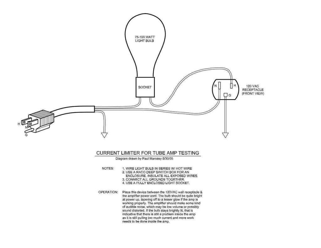
build yourself one of these:
Image
Use it every time you power up after a mod
Last edited by ironman28 on Wed Mar 05, 2014 10:35 am, edited 1 time in total.
User avatar
Tortuga
Crystal Lettucer
Posts: 17174
Joined: Sat Jan 19, 2013 11:29 am
Location: Slow and steady, bruh

Re: JCA50 Bias mod

Post by Tortuga »

ironman28 wrote:While you are in there replace the 470 ohm screen grid resistors with 1k 5W

build yourself one of these:
http://www4.picturepush.com/photo/a/107 ... miter1.jpg
Use it every time you power up after a mod


Question about changing the screen grid resistors. What exactly does this do? Will it affect tone in any way, or is it just for better amp efficiency / operation?

This current limiter link is awesome - thank you for that! I've heard about them, but not found this reference. Will be building one of these myself asap!

By the way, you can post the picture directly in here like this, by using the "Img" button above, and inserting the url path between the tags that pop up. Try it, you'll like it :D

Image
Co-founder of the Jet Setters 2.0 (Jet ★ City Lounge Redux)

Gear
  • CEOwLP (Sig T), Carvin DC135, Westone Spectrum SX (guitar) & GT (bass), Squier strat
  • '66 Bassman, '61 Magnatone, Mark III, 1960AX, homebrew 2x12 (C90 / EVM12L Thiele), HX Stomp, JCA50H
  • PLX GABion, SD-1, TS9, Crybaby, MXR108, Algal clone, Carbon Copy deluxe

DIY

Ostinato Rubato wrote:"That's the second boomery bro on this forum I've helped seduce to the greenside." :evil:

"Slow and steady gets to **** again eventually" :fap:
User avatar
Zozobra
Hall of Fame Member
Posts: 4811
Joined: Sun Jan 20, 2013 12:22 pm
Location: Manchestoh, UK

Re: JCA50 Bias mod

Post by Zozobra »

The screen grid resistors are there to protect the screen grids from over dissipation. At high power output the plates of the tubes swing to be at a lower voltage than the screens so some of the electrons strike the screen rather then the plate such that the screen starts pulling current from the cathode. The problem here is that the screens are fragile and can only dissipate a fraction of what the plate can (8W for an EL34, compared to the plate which can handle 25W) leading to screen failure. To mitigate this the screens grid resistor drops the voltage applied to the screen as the screen starts to pull current (V=I*R) which reduces the screen dissipation (P=I*V). The exact interaction is a bit more complicated than that but that is a good picture of what is happening. Some complication arises due to tube type: EL34's pull screen current well before full power due to their construction (true pentodes), where as other tubes types (beam/kinkless tetrodes) only pull significant screen current for high output. This is why EL34 amps tend to have 1K plus screen grid resistors and 6L6GC amps only have 460R.

Tonally increasing the screen grid resistor will increase power amp compression/reduce headroom as the screen voltage is the most important value in determining the output of a pentode power amp. Decreasing the voltage reduces power.

This sort of explains the effect of the screen voltage but the article is about the EF86 small signal pentode usually used in preamps:
http://www.valvewizard.co.uk/EF86.html
Loop wrote:I’m currently shopping for a 1996 Red Dodge Viper with yellow wheels. Who gives a shit about taste?!
User avatar
ironman28
Registered Member
Posts: 82
Joined: Sat Jun 01, 2013 10:46 am
Contact:

Re: JCA50 Bias mod

Post by ironman28 »

Zozobra wrote:The screen grid resistors are there to protect the screen grids from over dissipation. At high power output the plates of the tubes swing to be at a lower voltage than the screens so some of the electrons strike the screen rather then the plate such that the screen starts pulling current from the cathode. The problem here is that the screens are fragile and can only dissipate a fraction of what the plate can (8W for an EL34, compared to the plate which can handle 25W) leading to screen failure. To mitigate this the screens grid resistor drops the voltage applied to the screen as the screen starts to pull current (V=I*R) which reduces the screen dissipation (P=I*V). The exact interaction is a bit more complicated than that but that is a good picture of what is happening. Some complication arises due to tube type: EL34's pull screen current well before full power due to their construction (true pentodes), where as other tubes types (beam/kinkless tetrodes) only pull significant screen current for high output. This is why EL34 amps tend to have 1K plus screen grid resistors and 6L6GC amps only have 460R.

Tonally increasing the screen grid resistor will increase power amp compression/reduce headroom as the screen voltage is the most important value in determining the output of a pentode power amp. Decreasing the voltage reduces power.

This sort of explains the effect of the screen voltage but the article is about the EF86 small signal pentode usually used in preamps:
http://www.valvewizard.co.uk/EF86.html


This ^
The 1k value provides some protection for modern production valves that may not be as robust as a NOS valve. 1k is the rcommended minimum for an EL34 valve.
The key here is "high power output" or when you really start to push the output stage. Some amps, particularly those with EL84 outputs have no screen resistors at all. Small amps under 20 watts or so are typically operated under high output or clipping conditions to obtain PA distortion. EL84 screen grid resistors can be higher than 1k sometimes up to 2.7k.
I cannot hear :idk: the difference between a 470 ohm and a 1k screen grid resistance on high power amps 50 watts and over. The effects on smaller EL84 amps are distinctly audible as compression or a loss of high end detail. This might be beneficial to an overly bright amp to darken the tone.
Post Reply